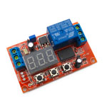
The program is selected using the FS button with indication in a circle from 1 to 18.
After the program is selected, we set the values of the variables delay "t" (and in some modes "t1" and "t2" and the number of repetitions "n" ) .
for this, press the "FS" button twice and on the display - the letter " t "or" t1 ".
To set t2, press the" FS "button twice after displaying" t1 ".
Press the" 8 Sel "button to select the indicator digit.
The "0-9 Sel" button selects the digit value of the digit.
The delay time 1-999 seconds or 1-999 minutes can be set by long pressing the "FS" button for a long time. When the letter "A" is released on the display, the setting ranges are 1-999 seconds. If the display shows the letter "b", the range is 1-999 minutes.
Input terminal of the trigger signal "IN "has an optocoupler isolation and by means of a jumper the actuation on low level" L "or high" H "is set.
To trigger the low level trigger circuit, you can short the "IN" input to the negative power wire.
After all settings have been made, you can turn off the display indication by pressing the "8 Sel" button for more than 3 seconds. The indication turns on with the same long press.
Module dimensions: 63.5 mm (l) * 38.5 mm (W) * 18.5 mm (H)
Operating current: 43mA Maximum current consumption 90mA.
Description of 18 programs:
Looped programs.
1. The relay is off when the power is turned on. When the trigger signal is applied, the relay is switched on for the time "t". Then it shuts down and waits for the next trigger signal.
2. When the power is turned on, the relay is energized. After the expiry of the "t" time, the relay is de-energized. When the trigger signal is applied, the timer is restarted.
3. When the power is turned on, the relay is switched on for the period "t1". Then the relay is de-energized for the period "t2". Then it stays on. When the trigger signal is applied, the t1 countdown is restarted.
4. When the power is turned on, the relay is off for the period "t1". Then the relay is switched on for the period "t2". Then it turns off. When the trigger signal is applied, the t1 countdown is restarted.
Looped programs:
5. At power-up, the relay is energized for the period "t1". Then the relay is de-energized for the period "t2". Then everything is repeated cyclically. When the trigger signal is applied, the t1 countdown is restarted.
6. When the power is turned on, the relay is off for the period "t1". Then the relay is switched on for the period "t2". Then everything is repeated cyclically. When the trigger signal is applied, the countdown t1 is restarted.
7. The variable "n" determines the number of cycle repetitions. The program is identical to program 5, repeated n times.
8. The variable "n" determines the number of loop repeats. The program is identical to program 6, repeated n times.
Triggered programs.
9. Power is always on. The relay is disabled. When the trigger signal is applied, the relay is switched on for the time "t", then it is switched off. During the countdown, the circuit does not respond to the repeated trigger signal.
10. Power is on continuously. The relay is disabled. When the trigger signal is applied, the timer "t" starts counting, then the relay is turned on. During the countdown, the circuit does not respond to the repeated trigger signal. At the next trigger signal, the cycle is repeated.
11. The program algorithm is identical to program 9, but when the trigger signal is repeated, the timer is restarted.
12. The program algorithm is identical to program 10, but with a repeated signal trigger, the timer is restarted.
13. Power is always on. The relay is disabled. When the trigger signal is applied, the timer "t1" starts counting, then the relay is turned on for the period "t2". During the countdown, the circuit does not respond to the repeated trigger signal. The cycle repeats on the next trigger signal.
14. Power is always on. The relay is disabled. When the trigger signal is applied, the relay is turned on and the timer "t1" starts counting, then the relay is turned off for the period "t2". then the relay turns on. During the countdown, the circuit does not respond to the repeated trigger signal. At the next trigger signal, the cycle is repeated.
15. The program algorithm is identical to program 13, but when the trigger signal is repeated, timer t1 is restarted.
16. The program algorithm is identical to program 14, but at repeated the trigger signal restarts timer t1.
17. Trigger mode. At the first trigger signal, the relay turns on, the next time it turns off. The circuit works according to the logic of the T-flip-flop.
18. Trigger mode. When the trigger signal is applied, the relay turns on when the trigger signal is removed, the relay turns off. The circuit works according to the logic of the Schmitt trigger.


 The data presented in the product description are for reference only and may differ from those indicated by the manufacturer.