This constructor was created on the basis of the projectSimple digital power regulator... The constructor contains the entire set of parts for assembling one regulator board (without housing).Devices of this type can be used to control lighting, the speed of fans (AC motors), and also to adjust the power of the soldering iron. Digital indication allows you to indirectly judge the amount of energy supplied to the load. The ability to save the specified parameters in the controller EPROMM eliminates the need for constant tuning when the device is turned on. The regulator not only remembers the set power, but also the current state. If you have set the state “oF” - off. Then, when power is applied, the regulator will be in the off state. If you turn it off in the on state (when the set power is displayed), then when the power is applied, the set power will also be turned on.
Regulator circuit.
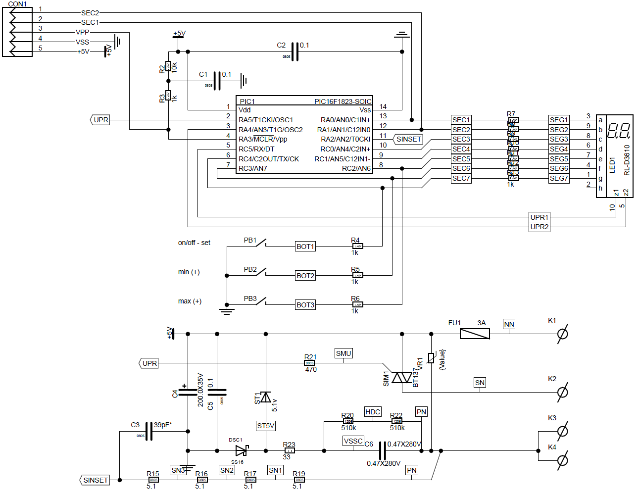
The regulator is assembled on a Microchip PIC16F1823 microcontroller. A capacitor power supply is used for power supply.
 ATTENTION... ALL ELEMENTS OF THE DEVICE ARE UNDER THE CAPACITY OF THE 230 VOLT NETWORK. BE ESPECIALLY CAREFUL WHEN ADJUSTING THE DEVICE.
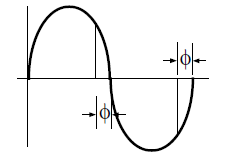
To control the power in the regulator, phase control is applied using a delay in the moment of turning on the triac. The zero crossing point of the mains voltage is used as the synchronization moment. As a synchronization pulse shaper, the properties of the microcontroller port are used to limit the value of the input voltage due to protective diodes. Consider the electrical circuit of the microcontroller port.

The 20 mOhm resistor limits the input current to an acceptable level, and the diodes limit the voltage to the power level of the microcontroller. The PIC16F1823 microcontroller has the ability to organize an interrupt for changing states at the inputs. For synchronization, we configure our input in the IOCAN: and IOCAF: registers to activate an interrupt on both the rise and fall of the signal. This gives us the opportunity to synchronize in each half-period.
To adjust the power, we need to change the moment when the triac is turned on.
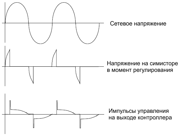
The principle is that the earlier we give a turning-on pulse after the moment of synchronization, the more power is supplied to the load. To adjust the power, we need to organize a delay for turning on the triac. For this we will use the TIMER1 timer.
The control principle is as follows, we use interrupts that can form a timer when it overflows. At the moment the synchronization pulse arrives, we preset the timer by the amount necessary to form our delay. And turn it on. The timer starts counting down, in case of overflow, the program switches to the formation of a triac control pulse (the timer is turned off). Then everything is repeated.
How the delay is mathematically formed. We use the controller at the maximum frequency (I love the maximum frequencies, since there is no need for this device to save consumption). Therefore, we can supply a clock frequency of 8 MHz to the timer input. If we set the prescaler to 8, then we get 1 MHz clock frequency at the input of the timers.
We use a power setting from 0 to 100%. And we need a 1% adjustment. The half-cycle duration of the 50 Hz network is (100 Hz) = 0.01 sec. Clock duration 0.000001 sec. In our case, we get that the timer will count 10,000 pulses in one half-cycle. At 1% of the power, we will have 100 pulses.
We have a 16-bit timer with a total value of 65535 (65536) pulses. To start forming the delay, we need to preset it by the value:
power_zag=65535-((100-power1)*100);
where: power_zag is the value that we load into the timer, power1 is the value for setting the power in% (0-100).
After the control pulse arrives, the triac opens and all the remaining power is sent to the load. At the moment the mains voltage crosses zero, the triac closes. Note that a “negative voltage” is used to drive the triac.
Power supply of the circuit.
Since for us there is no need for high power (but there is a need for powering the indicator) and it is assumed that the elements of the device during operation will always be protected from touch, the power supply of our circuit is made according to the scheme with a capacitor voltage divider.
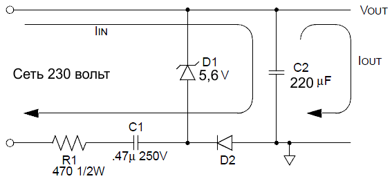
The device is powered through terminals K1 and K3, the load is connected to K2 and K4
Appointment of elements. Resistor R1 is designed to limit the maximum current through the zener diode at the moment the device is turned on or off, as well as at the moment when high-frequency interference may appear in the network for which the capacitor resistance becomes zero.
Capacitor C1 is our main current limiter for the Zener diode, which forms the supply voltage. For the negative half-wave, the zener diode completely passes the voltage, and for the positive half, it forms 5.6 volts on itself.
Diode D2 passes the positive voltage and charges the capacitor C2, which is used to power the microcontroller.
Set complete set:
1. Printed circuit boardch-c008-1 PC.
2. Microcontroller PIC16F1823 with firmware -1pc.
3. Indicator0.36 "2 digits, common anode-1 PC.
4. Clock button6 * 6 H-12mm-3 pcs.
5. TriacBT137-1 PC.
6. FuseF3.15A-1 PC.
7. Varistor07D471K-1 PC.
8. Capacitor0.47uf 280V-1 PC.
9. Resistor39R 2W-1 PC.
10. Zener diode1N4733A (5V1)-1 PC.
11. Capacitor220uf 25V-1 PC.
12. Capacitor0805 39pf -1 PC.
13. Capacitor0805 100nf (0.1uf)-3 pcs.
14. Resistor1206 510K-2 pcs.
15. Resistor0805 470R-1 PC.
16. Resistor0805 1K-11 pcs.
17. Resistor0805 10K-1 PC.
18. Resistor0805 5.1M -4 things.
19. DiodeSS26-1 PC.
